Design notes for adding an auto tune circuit to my 8-voice CrowBX synthesizer.
First we hear 8 times the same note with a long release tail so you can hear how out of tune it is. You hear 8 voices with 2 oscillators each, so 16 oscillators.
Then I tune oscillator 1 across all 8 voices, followed by oscillator 2. Then I play the same repeated note with a long release tail and we hear almost no beating.
Analog voltage controlled oscillators (VCOs) are temperature-sensitive. The CrowBX contains 16 VCOs. When the lid is closed they heat up. If I want to tune them by hand I need to open the lid which affects their temperature. An autotune circuit solves this problem by measuring and adjusting the tuning with the lid closed.
Contrary to more modern synthesizers, the autotune circuit I built needs a fair amount of human help. That is because many sound parameters in the CrowBX are under analog control. On modern synthesizers, with digital control, the autotune program can adjust the sound parameters to its needs while tuning. On the CrowBX, the user needs to adjust parameters and tell the autotune when it can go ahead and do its job.
Auto tune may fail if the desired pitch is out of range. If so the user must figure out which way to adjust manual tuning and try again.
MIDI in goes to autotune board first, from there as a "soft thru" to the MIDI-CV converter.
In:
|. MIDI 5 (CATHODE, 6N137 pin 3)
|. MIDI 4 (ANODE, 6N137 pin 2)
Out:
|. MIDI 5 (TX)
|. MIDI 4 (5V)
|. MIDI 2 (GND)
2x KK254-KK396 8-way cables carry tune CV's to host board.
Upper (sync PORTC1):
|. FT5A
|. FT5B
|. FT6A
|. FT6B
|. FT7A
|. FT7B
|. FT8A
|. FT8B
Lower (sync PORTC2):
|. FT1A
|. FT1B
|. FT2A
|. FT2B
|. FT3A
|. FT3B
|. FT4A
|. FT4B
4-way KK254-KK396 to power distribution board (+/-19V DC, 2x 0V).
|. P19V
|. 0V
|. 0V
|. N19V (NC)
Shielded patch cable (grounded on one end only) sends audio to audio input.
|. OSC MUX
|. NC
Incoming audio is 30V peak-to-peak AC. Use 1N4148 diode to rectify (positive half). Then passive voltage divider to bring peak level to 2-3V. Turn into 5V pulse with 2N3904 PNP transistor configured as a switch.
                    5V
                     |
                   [10K]
                     |
                    /C-- OUT
IN -->|---[10K]-+--B
                |   \E
              [2K2]  |
                |    |
               GND---+
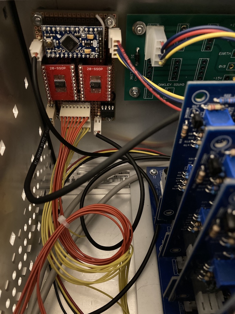
Total circuit is 1 diode, 1 transistor, 3 resistors. It fits in unused space under the Pro Mini board.
Expected reverse voltage for the rectifier is 15V which is well below the max of 75V for the 1N4148. With the voltage divider bringing the positive half down to 3V we are also well below the 5V collector voltage of the 2N3904 transistor.
I tried the circuit with a Schmitt trigger but the waveform did not look better than the simpler switch it is now.
Because the +/-12V board is over crowded, I used a 5V switch mode regulator from Traco Power. No capacitors needed, can regulate down from +19V main power rail to +5V with minimal heat loss.
Contrary to the MIDI-CV board, which outputs CV's from 0V-7V, we only need 0V-5V here. Because the DAC output buffers can operate rail-to-rail, we can run the whole board on just a 5V rail.
The AD5676R can be configured to output 0-5V (2x gain from its internal 2.5V reference). That is (almost) exactly the range I need to match what the OB-X used. So I don't need op-amp multipliers for each channel like on the MIDI-CV board.
Use polling to read MIDI IN and echo it to MIDI OUT. When the program changes to 127, stop echoing and treat note on messages as tune requests.
Assuming DAC monotonicity, use binary search to find correct tune CV.
Use Timer1 (16-bit) with input capture to measure the period of one oscillator cycle.
void tune_vco(uint8_t voice, uint8_t osc) {
    if ((voice >= NUM_VOICES) || (osc >= NUM_OSCS)) {
        return;
    }

    uart_tx(0x90 | midi_channel); // MIDI note on
    uart_tx(voice); // CV-gate board will play test note with this voice
    uart_tx(127);

    const double c_hz = 261.626;
    const uint16_t target_ticks = (F_CPU / 8.0 / c_hz);

    uint16_t value = 0;
    for (int8_t i = 15; i >= 0; i--) {
        value |= (1 << i);
        dac_send(voice, osc, value);

        if (tune_measure() < target_ticks) {
            value &= ~(1 << i);
        }
    }

    dac_send(voice, osc, value);
}