Usual warning: I am not an electronics expert. Things I write here may be completely wrong / off the mark.
The VCO's in the OB-X and the CrowBX are obviously nearly identical. The only differences I'm aware off are in the transistors and op-amps, for which the CrowBX uses modern parts. I also find it interesting how similar the VCO's are to those of the SEM. The SEM has more patch points / routing options, but otherwise the VCO's are virtually the same.
The OB-X has some asymmetry between VCO1 and VCO2. This is because VCO1 has a defeatable sync output, which connects to the discharge transistor of VCO2, and conversely, VCO2 has defeatable a saw wave output that feeds into the pitch CV summing amp of VCO1 ("cross mod"). Apart from this, OB-X VCO1 and VCO2 are the same.
I'll refer to CrowBX schematic part numbers for VCO1 below.
The design is a sawtooth relaxation oscillator. Pitch inputs are weighted and summed by an op-amp (one half of an LT1013 on the CrowBX). This feeds into a monolithic transistor pair configured as an exponential converter. The other half of the LT1013 maintains a constant current through the reference transistor of the exponential pair. The exponential current charges timing capacitor C8 that is connected to the +15V supply. This is different from typical oscillator examples where the capacitor is connected to ground and the output voltage ramps up from ground. Here it ramps down from 15V.
The sawtooth wave generated at the bottom of C8 is picked up by a buffer circuit. It uses three transistors: Q8 (a J112 JFET) as a low-resistance input, Q12 (J112) as a JFET current source, and Q10 (a 2N3906 PNP BJT) as an emiter follower. The emitter of Q10 is the output of the buffer. This buffer circuit is driven from the -15V / +19V rails. It cannot use the +15V rail because it needs to be more than a diode drop above the highest value of the saw wave which is 15V.
The buffered sawtooth is connected via a voltage divider and diode D2 to a Schmitt trigger consisting of Q14 and Q16. This Schmitt trigger creates a step change that activates Q6, the discharge transistor of the timing capacitor C8. I think the threshold mechanism of the oscillator is diode D2 going into conduction: this would pull Q14 out of saturation, Q16 into saturation, and from there, the discharge transistor Q6 also into saturation.
Interesting reference on exponential converters: Open Music Labs.
I sometimes forget the OB-1 as an evolutionary step between the SEM and the OB-X. The OB-1 introduced the microprocessor control that was such an important feature of the OB-X. It appears to have more or less the same oscillators, again.
One difference in the low pass filter: the SEM uses JFET buffers at the end of each filter pole. The OB-1 uses JFET's plus BJT emitter followers as buffers in the filter. The OB-X uses TL082 op-amp blocks as buffers. (The CrowBX uses TL072's instead of TL082's.)
The OB-1 also differs in that it has a 4-pole lowpass filter with switchable a 2-pole tap. It also has its own envelope generators that have digital logic and opamps, contrary to the SEM envelopes built out of transistors.
All three have the same discrete oscilators based on opamps and transistors.
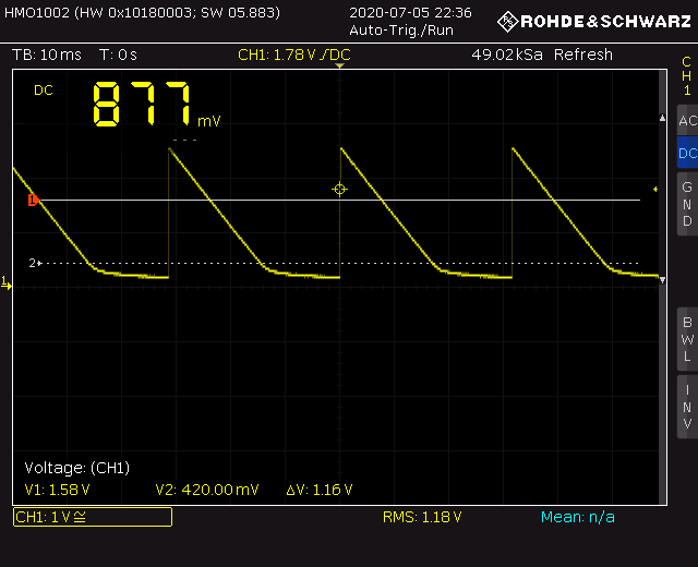
When testing VCO's with an oscilloscope I usually put the probe on the one diode in each VCO because it's easy to spot. Each VCO has one diode which is used to trigger the reset of the sawtooth core. I put the probe on the cathode of the diode (the side with the black band). The signal goes from roughly 0V to 2.5V and looks like this:
The saw is distorted by the diode at this point but it comes out clean at the end.
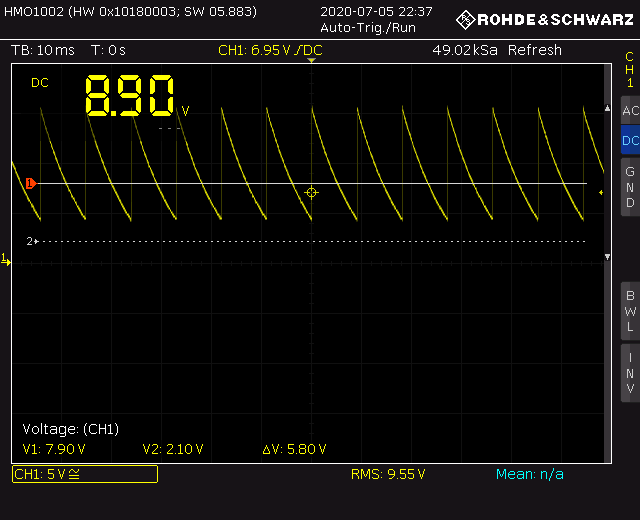
You can also measure at the gate of the input JFET of the buffer (equivalently, at the output of the exponential converter). In the picture below you can see that sticking the probe in there increased the frequency of the waveform. Here the saw goes from 15V down to about 4V.
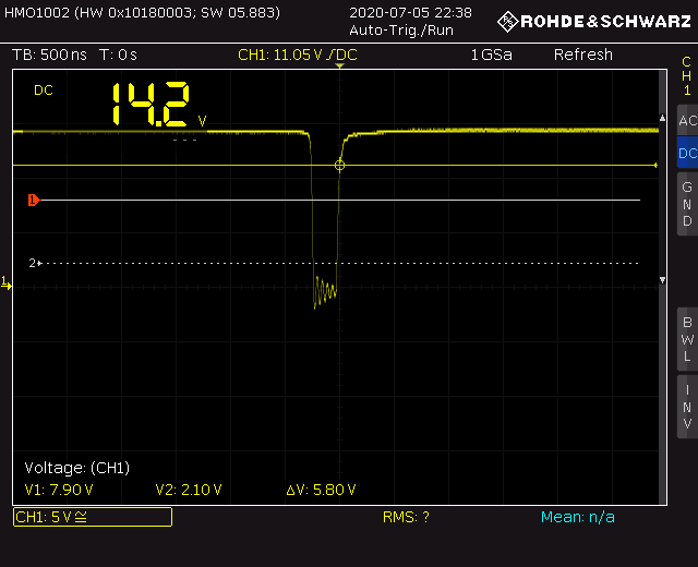
When the saw wave gets low enough, the Schmitt trigger kicks in, activating the discharge transistor of the capacitor. This resets the wave. The output of the Schmitt trigger is at the collector of a PNP transistor; it connects to a 1K resistor. At that collector you can see the following waveform. It is near 15V most of the time but it drops to 0V when the reset happens. The reset lasts for less than 500 ns.