I do not have drawings or schematics for the 8-voice backplane. All information on this page is based on reading, measuring and guessing.
Portamento is on pin 1 of connector BB, which would normally be ground. That means that BB is part of a Y cable: on the backplane, a 4-pin KK396, and on the host board side, an 8-pin and a 3-pin KK396. The upper 3 pins of BB go into the 8-pin connector. Pin 1 connects to what would be the pitch output of the host board if it were in single voice mode.
| Backplane | Host board | |
| BB1 | CC1 | portamento |
| BB2 | BB2 | cross-mod |
| BB3 | BB7 | PW1 |
| BB4 | BB8 | PW2 |
Pinout:
If my measurements are correct, the board is 10" by 11.05". Below are the drill holes in mm.
| 6.35 (0.25") | 134.62 (5.3") | 247.65 (9.75") | |
| 274.32 (10.8") | o | o | o |
| 203.2 (8") | o | o | o |
| 152.4 (6") | o | o | o |
| 101.6 (4") | o | o | o |
| 50.8 (2") | o | o | o |
| 7.62 (0.3") | o | o | o |
Facing the bottom of the board with the mixer section pointing up. I measured it like that because I want to make a mounting plate with countersunk holes, and those must be drilled from the bottom.
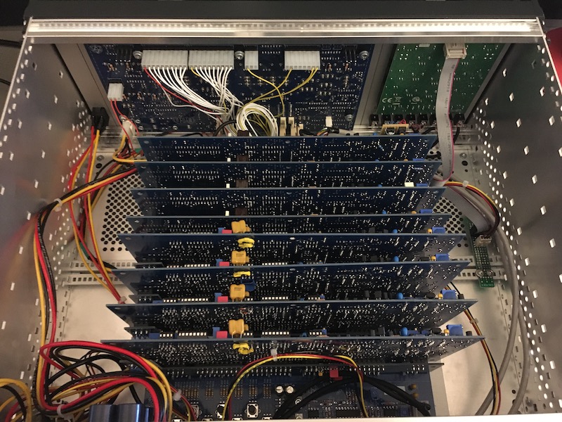
Here is the Front Panel Designer file I used to make a base plate that let me fit the 8-voice backplane into a 4U Schroff case. Note that the design is facing the bottom of the plate because it uses countersunk M3 screw holes.
You can see the basic design of the case below:
End result:
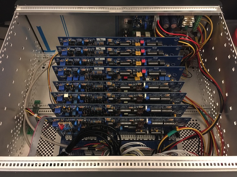
The green panel on the right is a Maths.
In each portamento circuit there is a 1nF capacitor (C11, C23, C26, C29 etc.). The PCB gives the option to either use a through-hole part or 0805 SMD. If you use through-hole then for 4 out of 8 of the 1nF capacitors you will be forced to bend the capacitor out of the way of the voice card connector. With SMD there is no such space problem.
As on the CrowBX host board (1-voice carrier) and the 4-voice carrier, Old Crow gives us the option to either use the same biased diode bridge as the OB-X to "perform linearization of the OTA inputs" or the internal linearizing diodes of the 13700's. That means:
For what it is worth I accidentally installed both on my 4-voice
and it works. But you do not actually need both.
Update: I checked and on my 4 voice carrier board I installed the diodes, not the 15K resistors. No idea what happens if you install both.
Connector GG is where you connect the volume control of the host board to the backplane. There is also an OSC MUX connection. This appears to be an output from the backplane which carries a mixed signal of all voice outputs. In the OB-X this is used by the auto-tune circuit. I think Old Crow was planning to design a host board with auto tune, this would explain why this signal is brought out on connector GG.
Update: I built my own auto-tune circuit that works with the 8-voice backplane.
The middle pin of GG on the host board is the volume CV. This should be connected to the volume pin of GG on the backplane. There is also an "XMUTE" output on the host board, which shunts the volume CV to ground on a 4 voice backplane. I see no corresponding function on the 8 voice backplane so I left XMUTE unconnected.
| Backplane | Host board | |
| GG1 | GG2 | volume |
| GG3 | GG1 | ground |
The slot adapters in my 4 voice contain a portamento circuit and a volume pan put. Both of these are also present on the 8 voice backplane, so I disabled them on the slot adapter.
Remove R1, R4, R5, R8, R9, R10, R11.
Install jumpers R6, R7, R14.
Wire the top of R4 to the top of R12 (ground). Wire the
right of R1 to the top of R12. This should tie the pitch input
and portamento input of the slot adapter portamento to
ground, stabilizing the circuit.
Do not install R12 itself, or you will short the portamento CV on the backplane to ground which is bad.
Update: Thinking about it some more, I should have left R4 alone. Removing it is OK but connecting one end to ground is not. What I wrote before shorted the Iabc input pin (amplifier bias current) of the LM13700 OTA used for portamento to ground. Inside the OTA Iabc passes through a diode to the -15V rail. This means that powering on the slot adapter will have greatly exceeded the maximum Iabc and that OTA is now broken. I think I will now just cut the TL072 and LM13700 IC's from the slot adapters. With portamento generated on the 8-voice backplane, I don't need them anymore.
As I was testing my sixth voice card I ran into a CrowBX host board bug I did not know about yet.
In this schematic you see that pin 5 of IC3 on the host board (a CD4011B quad NAND) is connected to bus D6_VCO2L. VCO2L is the CV that implements the "VCO2 half volume" mixer function. The problem is that that CV is not buffered. As you add more voice cards, you sink more and more current from the host board into the D6_VCO2L bus. At some point (in my case, at 6 voices) this prevents pin 5 of IC3 of ever going high, which is required for turning VCO2 off.
I solved this by adding a parallel 33K resistor to R22, the pull-up resistor for pin 5 of IC3. Effectively the pull-up is now 16K5 and it works gain.
Power consumption of the backplane with 8 voices plugged in (all AS3310) appears to be +575mA / -570mA. Note that original CrowBX voice cards, with the "CEM3310 equivalent circuit", would use more power.
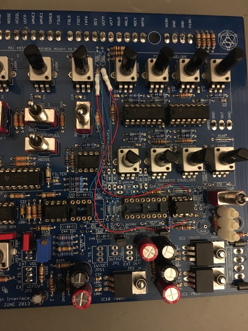
The VCFM (filter envelope amount) and resonance pots on the host board are not buffered. This works fine with 4 voices but with 8 it becomes a problem. At least with the filter envelope amount: you no longer get a gradual sweep on the pot, there is a steep drop somewhere in the middle.
I fixed this by buffering the pots with a TL072. I used the same circuit as elsewhere on the board: a 1K resistor between the pot wiper and the non-inverting opamp input, a jumper between the inverting input and the output, and a 10R resistor between the opamp output and the output pins (EE-5 and EE-6).
I put the TL072 in socket IC5, which is only used for a 1-voice host board and this unused in my case. IC5 has its non-inverting inputs shorted to ground, so I bent those pins (3 and 5) out of the socket. I think (hope) using 6 out of 8 pins is enough to mechanically connect the TL072 to the board.
IC5 is a bit out of the way of the VCFM and RES pots so I ended up with fairly long jumper wires. I was able to put the jumpers and the 10R resistors in empty positions on the PCB. The 1K resistors between the pot wiper and the op-amp inputs have only leg connected to the board; the other end is soldered to the jumper wire and hidden in heat shrink tube.